 English
 Italiano
Opto-isolated digital inputs: why they matter in industrial machinery
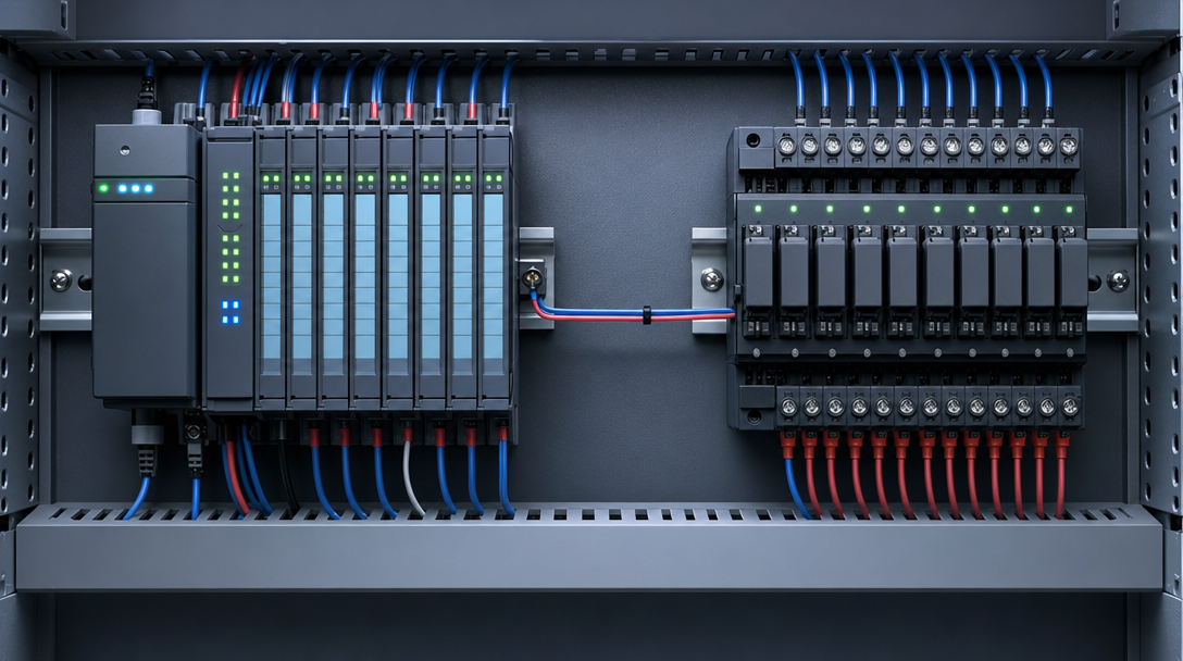
Have you ever spent hours chasing an intermittent fault on a machine that worked perfectly in the workshop? The PLC drops an input for a fraction of a second, the cycle stalls, the machine throws an alarm. You restart it, three shifts pass without incident, and then it happens again.
In a great many cases the culprit is not the software, not the sensor, and not any visible wiring fault. It lies in the way digital inputs read field signals in an electrically noisy environment. Opto-isolated digital inputs exist precisely for this reason: to place a physical and optical barrier between the field side, with all its interference, and the logic of your control system.
This article explains how that barrier works, when it is sufficient, and when it is not.
How optical isolation works in a digital input
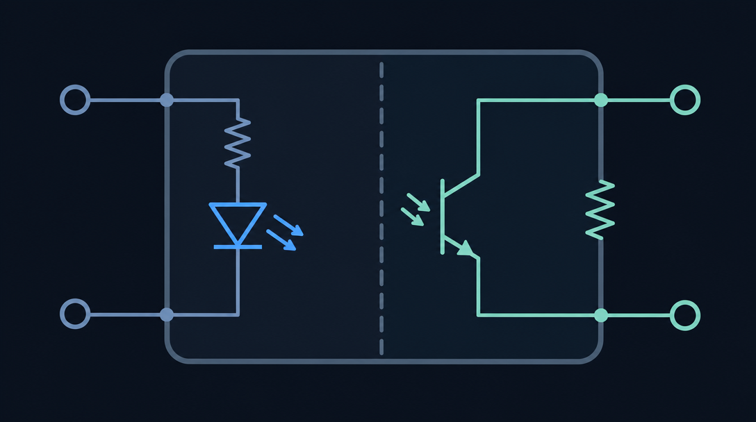
An optoisolator is a component that transmits an electrical signal via light. On the field side there is an infrared LED. On the logic side there is a phototransistor or photodiode. The two circuits never touch: the only link between them is the light beam inside the component.
This means the field earth and the logic earth are electrically separate. There is no direct conductive path between the two sides. This condition is called galvanic isolation, and it is the critical point.
What happens without galvanic isolation
If the inputs are not isolated, the field sensor earth connects directly to the logic board earth, which in turn connects to the communications bus, which runs back to the PLC or supervisory controller. Every disturbance on the field side, whether an electrostatic discharge, a transient induced by a contactor, or a common-mode current generated by a nearby inverter, has a clear path straight into the logic.
Common-mode disturbances are particularly troublesome. They do not appear as a voltage difference between the two signal conductors, but as a voltage that appears simultaneously on both conductors relative to earth. Differential circuits attenuate them, but do not eliminate them. Galvanic isolation blocks them at source, because there is no shared return path.
The isolation voltage: a figure worth checking
Datasheets often quote values such as 1500 V rms or 2500 V rms for isolation voltage. This is not the normal working voltage, but the maximum voltage the optical barrier can withstand without breaking down. For standard industrial applications, 1500 V rms is generally adequate. In environments with welding equipment, high-power motors, or medium-voltage switchgear nearby, it is worth verifying that the figure suits the specific installation.
Typical input voltages and switching thresholds
Not all opto-isolated digital inputs are designed for the same voltages. The most common configurations in industrial use are:
- 24 V DC - the de facto standard on most European automated machines, compatible with both PNP and NPN sensors
- 12 V DC - used in certain automotive applications and more compact systems
- AC voltages, typically 110 V or 230 V - required when inputs read directly from contacts on distribution networks or from unisolated manual controls
The switching threshold is not a single fixed value. IEC standards define bands of guaranteed logic state. For 24 V DC signals to IEC 61131-2, logic 0 is guaranteed below 5 V and logic 1 is guaranteed above 15 V. The band between 5 V and 15 V is undefined: a well-designed input must ignore signals in that range rather than interpret them arbitrarily.
This detail becomes significant when the signal cable is long, has non-negligible resistance, or when the sensor has internal leakage that reduces the actual voltage at the input terminal.
Difficult environments: inverters, motors, and welding equipment
The environment around an industrial machine is far from electrically neutral. The most aggressive interference comes from three main sources.
Inverters and variable-speed drives
An inverter generates high-frequency transients on the motor cable. Where signal wiring runs parallel to power cables for any appreciable distance, the electromagnetic field induces parasitic voltages on the signal conductors. These voltages can be fast enough to cross the switching threshold for fractions of a millisecond, which is sufficient to convince the controller that an input has changed state.
The optoisolator alone does not solve everything. Input filtering, typically an RC filter with a time constant in the order of one millisecond, works alongside the isolation to suppress these brief spikes. A well-designed I/O module implements both.
Direct-on-line motor starting
When an induction motor is started direct-on-line, the inrush current peak generates a fluctuation on the supply voltage and a pulsed magnetic field. If the cabinet is not properly screened, this disturbance reaches the digital inputs as a potential variation on the field common.
Resistance and arc welding equipment
Welding equipment represents the most demanding scenario. Current spikes are extremely brief but have a very steep rate of rise. Circulating currents in the metal structures of the machine can generate potential differences between points that appear to be connected. In these environments, galvanic isolation of the inputs is not merely a precaution: it is a minimum requirement.
Noise immunity to IEC 61000
The IEC 61000 series defines the tests an industrial device must pass to be declared immune to electromagnetic disturbances. The most relevant for I/O modules are:
- IEC 61000-4-2 - electrostatic discharge (ESD), up to 4 kV contact discharge
- IEC 61000-4-4 - electrical fast transients (EFT/Burst), covering the high-frequency transients generated by contactors and inverters
Related insights

Modbus RTU or Modbus TCP: which protocol should you choose for your installation?
Before you pull cables or select an I/O module, it is worth pausing for a moment. Modbus RTU RS485 and Modbus TCP over Ethernet are both solid, widely supported …
Read further